Basic Dot Matrix-Finally saia to write again after so long afflicted with laziness .. : P n now i want to scream: GO OPEN SOURCE! why open source? yup because science is from the Lord .. so why should you pay? 
Well, now I want nge-share on the basics of LED Dot Matrix (base aja, klo to the expert level, please ask the experts .. which is definitely not me .. hehe) Dot Matrix is actually composed of multiple LEDs are arranged in a matrix (consisting of columns and rows). why matrix?
Just try to imagine, to make any necessary letters 1 piece 5x7 pixel LED, meaning it takes 35 LEDs. if not arranged in a matrix would be wasteful PORT. was only one character, just imagine if we want to make 20 characters?
Typically, these components are sized 5x7 or 8x8, and so the module can be either made themselves or by arranging a few LEDs. The size is also all kinds, there is a large, medium and small.
Physically, the shape as shown below (medium size):
Physically, the shape as shown below (medium size):


like this if schematic form:

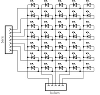
Typically, the components that I bought (in Yogyakarta) has a line configuration of Anode (+) and the columns of cathode (-). so, to turn all his dot, all lines must be logic 1 (high) and logic given column 2 (low). yup by now wrote his theory, now let's play around a dot matrix .. how ya about how to turn it all DOT?
key is Scanning the process ..
here, I use a 5x7 LED dot matrix so (modules) are contained in small size module Technovision AVR Development Board V2.1
or, it could make your own. something like this:


for normal use eagle u / make PCB, just use eagle files (5.4.0 and above) contains a schematic, board, and my library from below ..
monggo in the download ... FREEEEEEE .. eagle design 5x7 Dot Matrix
or more extreme, let me quickly so, use the PCB hole aja ama cable (sorry, no pict, have never tried it .. hehe)
I am using AVR ATMEGA8535 here. To connect to the microcontroller, we connect the line to PORTC.0 - PORTC.6, columns to PORTD.0 - PORTD.4
scheme: (I made pake proteus, but can not be simulated because the scanning is too fast)
also download the source code:
source code BASCOM - DOT MATRIX
then, compile and download the program to your UC. then what happens?
all DOT should be lit. how come you know? This is called the scanning process.
PORT column we turn one on one to give a logic 0 in turn. PORT active when this column, we give the pin a logic 1 in each row. This makes the process of scanning all the DOT is on .. when it actually turns .. believe guns? try changing the delay on a piece of the program ..

Now turn the flame right?
so much from me, InsyaAlloh in the next article I will discuss about how to make the letters / numbers / symbols on a dot matrix and animated.
Basic Dot Matrix


