 |
| graphic LCD at89s51 keil code |
The most character LCD module can be interface with microcontroller in any of these two ways of interface:
1. 4-Bit Interface
( a little bit slow LCD interface but we can safe the data input/output lines of micro-controller for other use, i.e. to interface other hardwares to it.
2. 8-Bit Interface
( This is speedy LCD interface method to any microprocessor or microcontroller, more using this interface method, one can easy develop a program in c++/C or VB6 to directly interface a character LCD with PC parallel port, some it requires in certain application.)
Graphic LCD Module:
But The Graphic LCD Module requires 8-bit data bus (DB0 – DB7). The Graphic LCD Module is normally ( foreample JHD12864J ) splited logically into two portions. One half with controller #1 (CS1) driving the left half of the display, and controller #2 (CS2) driving the right half. These two portions map directly to the physical display areas of graphic LCD. With a correct controlling sequence on pin CSx (x=1,2), D/I, and R/W, we can write any pattern, image, animation , and text in bigger fonts directly to the LCD screen at a designated column position.
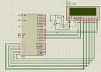
The Interface of a Graphic LCD with micro-controller 8051 family.
Here we will discuss, the interfacing of GLCD (Graphic LCD module ) with micro-controller 8051 family only, I have used At89s52 in this project but you can use any micro-controller of 8051 family like at89c51 or at89c2051 , it will work with all (hopefully but not granty). There are two ways to interface the LCD with AT89S52:
1. Address/data bus memory map, i.e. use the LCD as a piece of external RAM
2. Direct I/O connection by writing high/low signal to LCD.
The first of all, we start with a task to understand the control sequence required to read or write data to the LCD module. There are several points, instruction, steps and sequences to show a graphic data or image on graphic LCD. Most common and important of them are described here as follows:
1. RS controls data or command action (D/I=LOW ? command; D/I=HIGH ? data).
2. Horizontal pixel addressed by Y address counter (0-63). The Y address indicates the column position in the horizontal direction. As, earlier describes the LCD is splitted logically in half with controller #1 (CS1) driving the left half of the display, and controller #2 (CS2) driving the right half. So the range of Y address counter is from 0 to 63, (128/2 = 64).
3. The term Page refers to 8-pixel vertically. There are 8 pages ranging from 0 to 7, thus matching a vertical matrix size of 64 pixels.
4. R/W controls data READ / WRITE (R/W=LOW ,, write; R/W=HIGH ,, read).
5. CS1, CS2, E, and RST pins are also control PINs of Graphic LCD. Direct low-level access and signal timing requirement will be taken care by hardware dependent functions.
 |
| Graphic LCD 8051 microcontroller |
 |
| Graphic LCD interface with microcontroller |